A microstrip reflectarray is a low-profile, inexpensive antenna which combines some of the best features of reflectors and microstrip arrays [1, 2]. Reflectarray surface which consists of isolated radiating elements is illuminated by a feed antenna. These radiating elements (patches or dipoles) are pre-designed with a particular phase delay such that the illuminating electric field from the feed will be re-radiated and scattered from these elements to form a prescribed phase front in front of the aperture. The reflectarray concept is based on the scattering properties of these radiating elements. There are several different ways to control the phase of an individual element. Some of them are - microstrip patches with the same shape and size loaded with variable length stubs [1], variable size dipoles or microstrip patches, microstrip patches with same shape but different sizes [3], identical microstrip patches on the top layer loaded with variable length slots on the ground plane [4].
The concept of reconfigurable reflectarray element is beneficial for reflectarray design as it allows for dynamic phase control of a single radiating element. Each radiating element can have a similar physical structure and the desired phase response can be achieved by electronically manipulating each element. This reconfigurable reflectarray using MEMS switches can be used as a subreflector to compensate for the distortions on the main reflector as shown in Fig. 1. This is a novel concept with future applications. The passive reflectarray can only compensate for static distortions on the main reflector while the reconfigurable reflectarray can compensate for both the static and dynamic distortions. The purpose of this paper is to investigate potential reflectarray elements by taking into consideration the eventual implementation of MEMS technology for this particular application and detailed characterization of one of the potential element designs.
Reflectarray element: Variable slot on the ground plane
Different reflectarray designs were studied for this particular application as shown in Fig. 2. It was decided that the element with variable slot on the ground plane was best suited keeping in mind the MEMS implementation. The detailed characterization of the element involved testing the concept of reconfigurability and measurement of the phase response of a unit cell design. The principle of operation of the reconfigurable microstrip slotloaded patch reflectarray shown in Fig. 3 (a) is as follows. Radiating patch elements of equal sizes are printed on the top layer and a slot of fixed length is cut in the ground plane of each element. RF MEMS switches are implemented on the slot and length of the slot is changed by turning the switches ON/OFF. In absence of the slot, each patch radiates at its resonant frequency. The presence of slots acts as an inductive loading and introduces a phase shift. Thus, the phase of the reflected field from each unit cell of the reflectarray can be changed by determining the location of the RF MEMS switches.
Reflection Phase: Simulation and Measurement Results
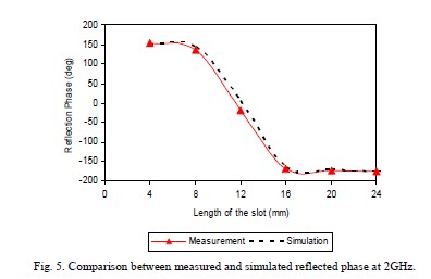
Fig. 3 (b) shows the HFSS simulated model of the reflectarray element. Waveguide simulation approach was used in HFSS. Fig. 4 (a) shows the measurement setup. Figs. 4 (b) and (c) show the sample with different effective slot lengths attached to the S-band waveguide. The slot length was fixed and copper strips were used as shorting switches to reduce the effective length of the slot. The frequency (f) of operation was 2GHz (angle of incidence = 43°). The free space wavelength (λ) was 15cm and guided wavelength (λg) was 10.11mm). The unit cell size was 10.9cm x 5.5cm. Substrate with 31 mil thickness and dielectric constant of 2.2 was used. The patch size on the top layer was 4.7cm x 4.7cm (0.47 λg x 0.47 λg). The slot width on the ground plane was fixed to 0.28mm (0.028 λg). The dimensions of the copper strips (switches) were 1.5mm x 5mm. The dimensions of commercially available MEMS switches are around 1.5mm x 1.5mm. The copper strips (switches) used in the present design have the same width (1.5mm). The dimensions of the patch and the slot were chosen such that the patch is in resonance and the slot does not radiate. The only purpose of the slot is to load the patch and change the phase of the reflected field. Fig. 4 shows the comparison between the simulated and measured reflection phase results for the frequency of 2GHz. It can be seen that there is a very good agreement between the measured and simulated results. This verifies the reconfigurability concept for the design. Present efforts are on to integrate the commercially available switches in the present design and measure the reflection phase and also study the losses associated with the present geometry.
Reconfigurable feature offers electronic control of each element which provides for easier implementation of the whole reflectarray system. Several potential reflectarray element designs were investigated with critical importance given to the consideration of MEMS implementation in the final design. The reflectarray element with variable slot on ground plane and fixed patch on top was selected for final characterization. The concept of reconfigurability was tested for this design, unit cell of this reflectarray was fabricated and tested, and reflection phase measurements were performed. Future work includesmplementation of the actual switches models (MEMS) in the simulation, characterization of losses and development of an addressing scheme for the switch
The concept of reconfigurable reflectarray element is beneficial for reflectarray design as it allows for dynamic phase control of a single radiating element. Each radiating element can have a similar physical structure and the desired phase response can be achieved by electronically manipulating each element. This reconfigurable reflectarray using MEMS switches can be used as a subreflector to compensate for the distortions on the main reflector as shown in Fig. 1. This is a novel concept with future applications. The passive reflectarray can only compensate for static distortions on the main reflector while the reconfigurable reflectarray can compensate for both the static and dynamic distortions. The purpose of this paper is to investigate potential reflectarray elements by taking into consideration the eventual implementation of MEMS technology for this particular application and detailed characterization of one of the potential element designs.
Reflectarray element: Variable slot on the ground plane
Different reflectarray designs were studied for this particular application as shown in Fig. 2. It was decided that the element with variable slot on the ground plane was best suited keeping in mind the MEMS implementation. The detailed characterization of the element involved testing the concept of reconfigurability and measurement of the phase response of a unit cell design. The principle of operation of the reconfigurable microstrip slotloaded patch reflectarray shown in Fig. 3 (a) is as follows. Radiating patch elements of equal sizes are printed on the top layer and a slot of fixed length is cut in the ground plane of each element. RF MEMS switches are implemented on the slot and length of the slot is changed by turning the switches ON/OFF. In absence of the slot, each patch radiates at its resonant frequency. The presence of slots acts as an inductive loading and introduces a phase shift. Thus, the phase of the reflected field from each unit cell of the reflectarray can be changed by determining the location of the RF MEMS switches.
Reflection Phase: Simulation and Measurement Results
Fig. 3 (b) shows the HFSS simulated model of the reflectarray element. Waveguide simulation approach was used in HFSS. Fig. 4 (a) shows the measurement setup. Figs. 4 (b) and (c) show the sample with different effective slot lengths attached to the S-band waveguide. The slot length was fixed and copper strips were used as shorting switches to reduce the effective length of the slot. The frequency (f) of operation was 2GHz (angle of incidence = 43°). The free space wavelength (λ) was 15cm and guided wavelength (λg) was 10.11mm). The unit cell size was 10.9cm x 5.5cm. Substrate with 31 mil thickness and dielectric constant of 2.2 was used. The patch size on the top layer was 4.7cm x 4.7cm (0.47 λg x 0.47 λg). The slot width on the ground plane was fixed to 0.28mm (0.028 λg). The dimensions of the copper strips (switches) were 1.5mm x 5mm. The dimensions of commercially available MEMS switches are around 1.5mm x 1.5mm. The copper strips (switches) used in the present design have the same width (1.5mm). The dimensions of the patch and the slot were chosen such that the patch is in resonance and the slot does not radiate. The only purpose of the slot is to load the patch and change the phase of the reflected field. Fig. 4 shows the comparison between the simulated and measured reflection phase results for the frequency of 2GHz. It can be seen that there is a very good agreement between the measured and simulated results. This verifies the reconfigurability concept for the design. Present efforts are on to integrate the commercially available switches in the present design and measure the reflection phase and also study the losses associated with the present geometry.
Reconfigurable feature offers electronic control of each element which provides for easier implementation of the whole reflectarray system. Several potential reflectarray element designs were investigated with critical importance given to the consideration of MEMS implementation in the final design. The reflectarray element with variable slot on ground plane and fixed patch on top was selected for final characterization. The concept of reconfigurability was tested for this design, unit cell of this reflectarray was fabricated and tested, and reflection phase measurements were performed. Future work includesmplementation of the actual switches models (MEMS) in the simulation, characterization of losses and development of an addressing scheme for the switch


Jorge Polentino
CRF
196769972
http://www.ee.ucla.edu/~harish/C9-IEEEAP-07.pdf
No hay comentarios:
Publicar un comentario