Recent advancements in the field of wireless communications have dictated the need for new micromechanical RF components capable of multi-frequency low-loss filtering and frequency synthesis on the same silicon chip. The growing demand for newer functionalities and applications has crowded the frequency spectrum to the point that several RF bands are now closely spaced within a few MHz. These needs translate in performance requirements in terms of insertion losses, rejection, integration and quality factor that state-of-the-art resonator technologies such as SAW and FBAR can hardly meet altogether. A new class of vibrating RF MEMS resonators [1-4] has emerged as a potential solution for next generation wireless communications. These devices, either electrostatically or piezoelectrically transduced, are bulk acoustic wave resonators that have their fundamental frequency set by their in-plane dimensions and therefore dubbed contour-mode resonators. They have already demonstrated high quality factors (up to 10,000 at GHz), small size, good linearity, and especially the ability to span frequencies from few MHz up to GHz on the same silicon chip. Amongst this new class of resonators, AlN contour-mode vibrating RF micromechanical devices constitute the most promising technology capable of immediately satisfying the emerging needs of the wireless industry. AlN contour-mode resonators are the only structures capable of spanning frequency from 10 MHz up to almost GHz (in their fundamental mode of operation) on the same silicon chip and demonstrating impedance values on par with existing technologies and therefore readily matched to 50 Ω RF systems. This paper describes this new class of AlN contour-mode resonators and presents initial experimental results using these devices for circuit applications such as band pass filtering and frequency synthesis. Furthermore, these vibrating RF MEMS components will enable new architectures for RF front-ends characterized by reduced power consumption and faster switching speed levels. The ability to batch fabricate filter banks at different frequencies will deliver compact and highly integrated solutions capable of frequency hopping and direct frequency synthesis in next generation reconfigurable radios.

II. ALN CONTOUR-MODE RESONATOR TECHNOLOGY
Contour modes of vibration are excited in c-axis oriented aluminum nitride films via the d31 piezoelectric coefficient. By applying an alternating electric field across the film thickness the AlN MEMS structure expands and contracts laterally and can be excited in resonant vibrations whose frequency is set by the in-plane dimensions of the device. The frequency of vibration is generally set by the width of the structure, whereas the second dimension can be employed to control the equivalent motional resistance and static capacitance of the device. Frequency setting via lithographic techniques enables the definition of multiple frequency devices on the same substrate and drastically reduces manufacturing tolerances on film thickness (by 10x) that are instead currently demanded by commercially available technologies such as FBARs and quartz shear resonators.
A. AlN Contour-Mode Resonators
Figure 1 schematically presents the range of operation for the three most promising device topologies developed to date for contour-mode AlN resonators. Rectangular plates, rings and higher-order contour-mode plates can be fabricated in the same process. According to experimental results, manufacturing considerations and theoretical observations (structural rigidity), and in order to achieve impedance levels that can be readily interfaced with 50 Ω RF systems:
- the rectangular plate geometry [5] can be effectively employed from 10 to approximately 100 MHz;
- the ring geometry [3] can be adopted between 100 and 400 MHz;
- the higher-order contour-mode rectangular geometry [7] can be used between 400 and 2,500 MHz.
Although based on preliminary results and subject to improvements through future research, these guidelines offer a good prospective of the status and range of applicability of the AlN contour-mode technology. As shown in Figure 2 these resonators are capable of Q as high as 4,300 in air, have motional resistances ranging from 25 to 700 Ω, figure of merit (FOM = Q·kt^2) close to 40 and can especially span a broad range of frequency from few MHz up to almost GHz on the same silicon chip.
B. AlN Contour-Mode Oscillator and Filters AlN
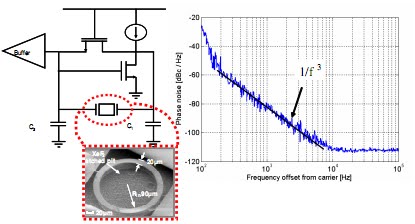
Contour-mode resonators have been demonstrated in circuit based applications for frequency synthesis and band pass filtering. Differently from all the other electrostatic MEMS resonator-based oscillators [8], a standard pierce circuit design that does not require automatic gain control or pump charge (no DC voltage is required by piezoelectric actuation) was employed. A 224 MHz circular ring with Q of 2,300 was wire bonded to the circuit realized in 0.25 µm CMOS technology (Fig. 3). Preliminary results are showing respectable phase noise performance of ~ - 110 dBc/Hz at 10 kHz offset. Although the consumed power is relatively high (2.5 mW total), it is expected that further optimization will reduce the power level to few hundreds µW.

AlN contour-mode resonators have also been either electrically or mechanically coupled to form VHF band pass filters. Table I summarizes the most significant experimental results that were obtained by arraying these resonators. Electrically coupled ladder structures are easily implemented and have proven highly reliable in the demonstration of high order filters (up to 8 resonators were coupled). Insertion losses as low as - 4 dB have been achieved at 93 MHz using 8 rectangular plates that occupy a fraction (~ 30x area saving) of the board space taken by existing IF SAW filters. Mechanical coupling of resonators has produced filters with the lowest insertion loss level of - 1.5 dB and has the advantage of making possible the definition of the filter bandwidth directly at the lithography level. The bandwidth is in fact proportional to the ratio of the stiffness of the coupling beam and the resonator stiffness at the coupling location. These parameters can be defined at the CAD layout level, differently from the case of electrical coupling for which the bandwidth is instead set by material properties (kt^2). The implementation of IF filters via AlN contour-mode resonators not only shows the possibility to bring back into fashion low-power super-heterodyne architectures based on IF filter stages, but also sets the path for realizing new classes of on-chip RF front-ends based on large scale integration of micromechanical components.
Figure 2. Examples of the electrical response of AlN contour-mode resonators. From left to right:admittance plot of a 200x50 µm rectangular plate; admittance plot for a 20 µm wide circular ring with 100 µm average radius; admittance plot of 100x51 µm higher-order contour-mode plate.
 Table I. Performance summary of electrically and mechanically coupled IF filters realized using AlN contour-mode micromechanical resonatorsonators

III. MEMS-BASED RF FRONT-ENDS
 Narrow bandwidth filters can also be employed for direct frequency synthesis in spread spectrum applications. Instead of using power-hungry tunable PLL, the frequencies are produced by generating a train of pulses from a low-noise reference source and selecting among signals processed through banks of filters (Fig. 5). In this manner faster switching speed and lower power consumption level than using indirect frequency synthesis methods based on PLL can be achieved. Direct frequency synthesis could also be pursued more aggressively by using switched banks of high Q (Q ≥ 10,000) and high frequency resonators eliminating the need for a low noise reference source and overall occupying a smaller chip area.
 Jorge Polentino
As already stated, AlN contour-mode resonators will have a tremendous impact on the wireless industry by providing smaller size and lower power RF components that can directly replace bulky and unintegrable (non silicon based) legacy technologies such as SAW and quartz crystals. Significantly more performance gains are to be achieved by large scale integration of multiple frequency micromechanical devices on the same substrate. By massively arraying banks of closely spaced (in frequency) band pass filters it is possible to easily implement frequency hopping spread spectrum (FHSS) ransceivers (Fig. 4). This MEMS implementation will go beyond currently available FHSS transmission standards by spanning ultra wide bandwidth (as wide as 1 GHz) and occupying a very small board area (would instead occupy an mpractically large area with current multi-package SAW or FBAR technology). This solution will provide improved SNR and lower power consumption levels and at the same time will ncrease transmission capacity and security.
 Narrow bandwidth filters can also be employed for direct frequency synthesis in spread spectrum applications. Instead of using power-hungry tunable PLL, the frequencies are produced by generating a train of pulses from a low-noise reference source and selecting among signals processed through banks of filters (Fig. 5). In this manner faster switching speed and lower power consumption level than using indirect frequency synthesis methods based on PLL can be achieved. Direct frequency synthesis could also be pursued more aggressively by using switched banks of high Q (Q ≥ 10,000) and high frequency resonators eliminating the need for a low noise reference source and overall occupying a smaller chip area.
 Jorge Polentino
CI 19769972
CRF
No hay comentarios:
Publicar un comentario